Why Not Using SWDM Technology Over OM5 Fiber?

Although optical parallel transmission is direct, simple and effective to transmit big data, it is not very recommendable as its cabling cost would be very high for the multiple optical lanes. Then what should we do when we need high capacity network for big data transmission? In this post, it is highly recommended to utilize SWDM (shortwave wavelength division multiplexing) technology as a cost effective solution that offers each fiber at least four times higher capacity for meeting our needs. As shown in the following figure, SWDM technology can multiplex at least four short wavelengths in the 850-950nm range over a single strand of duplex OM5 fiber, so that more than four virtual lanes can be created for optical transmission.

SWDM over OM5

Benefits of SWDM Technology Over OM5 Fiber

Undoubtedly, SWDM technology is a cost effective solution for 40G, 100G or even higher connectivity over duplex multimode fiber, especially OM5. With regard to the benefits of SWDM technology, it is shown below:

Transmission Distance–When using SWDM technology for 40G connectivity over OM5 fiber, the transmission distance can be up to 440 m; for 100G connectivity, the transmission distance can be 200 m at most. Besides, SWDM technology can also support 40G connectivity over OM3 and OM4 at lengths up to 250 m and 350m, respectively.

Excellent Design–Firstly, the Full DDM enables five digital diagnostics functions, temperature, voltage, bias current, Rx power, and Tx power. Secondly, the single Tx and Rx ports enable easier operation and measurement. Thirdly, the simple Tx and Rx port design also makes network security appliances easy and fast.

Power Dissipation–Compared to SR4 optic, the SWDM optic has a lower power dissipation for matching the 4x WDM optical architecture with 4x electrical interface. In general, the power dissipation of QSFP+ SWDM4 can be as low as 1.5W, so that QSFP+ SWDM4 can be also used in the applications with QSFP+ SR4 standard.

40G SWDM4 vs 100G SWDM4 vs 100G SWDM2

With the introduction of OM5 fiber, the multimode fiber cabling system becomes much more popular than ever before. To meet the multimode fiber cabling system needs, multimode SWDM transceiver series including 40G SWDM4, 100G SWDM4 and 100G SWDM2 were published in succession, which are less expensive but have more efficient power consumption, compared to singlemode transceivers.

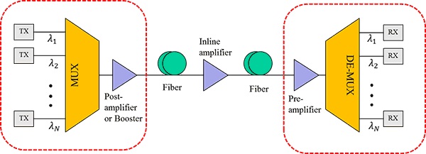
40G SWDM4–It is a typical kind of QSFP+ transceiver, designed with duplex connector, which always works with duplex-LC OM5 fiber. Since SWDM technology is used in this kind of QSFP+ transceiver, a 40G connectivity can be easily achieved with the use of a pair of 40G SWDM4 transceivers and a length of duplex-LC OM5 fiber cable. When the 40G connectivity is working, four 10G signals with different wavelengths (850nm, 880nm, 910nm and 940nm) are multiplexed at the transmitter end, transmitted through the OM5 fiber cable and finally demultiplexed at the receiver end, as shown in the following figure.

40G SWDM4 Transceivers

100G SWDM4–It is a QSFP28 standard transceiver with duplex connector used for 100G connectivity. Its working principle is very similar to 40G SWDM4 that can be easily learned from the figure below. In simple words, the total 100G connectivity is done by multiplexing four 25G signals with the same four wavelengths (850nm, 880nm, 910nm and 940nm) over duplex -LC OM5 fiber cable.

100G SWDM4 Transceivers

100G SWDM2–Compared to 100G SWDM4, the 100G SWDM2 transceiver has a easier working principle which only multiplexes two different wavelengths (850nm and 910nm) for carrying two 50G signals over the duplex -LC OM5 fiber cable. Hence, a 100G connectivity can be totally reached.

100G SWDM2 Transceivers

Uncertainty of SWDM Technology Over OM5 Fiber

Although the SWDM technology over OM5 fiber brings us so many benefits, there are still some uncertain factors existing that prevent the SWDM technology from being widely adopted. Above all, the SWDM technology is not mature enough to support our needs at present. The factors including SWDM transceiver complexity, the power consumption and the total cabling cost using SWDM technology are the potential obstacles. Meanwhile, the SWDM connectivity is not so flexible as the parallel connectivity and can’t support breakout configuration in the short-reach cabling systems. Once these uncertainty are solved, the SWDM technology will be more and more mature for widely use.

Would You Choose OM5 for Data Center Cabling?

It is recognized that multimode fiber cable (MMF) is always a cost-effective cabling solution for short distance transmission, including OM1, OM2, OM3 and OM4. Nowadays an updated type of multimode fiber cable named OM5 has gained widespread attraction among researcher and specialist in optical communication. Is this kind of MMF cable also a good choice for data center cabling? What are the main differences between OM1, OM2, OM3, OM4 and OM5? Can OM5 perform better than OM4 and other MMF cables? Let’s explore the answers.

Would You Choose OM5 for Data Center Cabling

OM5 Overview

OM5 is a new 50/125µm multimode optical fiber mainly designed for 40G and 100G data center standardized by TIA and IEC and released in last June. Then in this February, the color of OM5 has also identified, lime green, which is different from that of other MMF cables. Also, the color for OM5 connector and adapter housing should be different for easy identification. However, the OM5 connector and adapter types don’t change which means OM3 and OM4 connector and adapter are still suitable for OM5.

OM5 was initial called wideband multimode fiber (WBMMF) because it specifies a wider range of wavelengths between 850nm and 953nm at the same time for Wavelength Division Multiplexing (WDM) application, while other MMF cables are always used to support one wavelength a time. The WDM technology utilizes OM5 can be called SWDM (the letter S stands for shortwave). Due to this feature, OM5 enables a higher bandwidth network cabling that supports 40G, 100G and beyond.

OM1, OM2, OM3, OM4 vs OM5

As we know, OM1 is the only one 62.5/125um MMF cable always used in 1G application, while OM2 has a smaller core diameter, 50um that supports 1G network at a longer length, 550 m. Different from these two MMF cable mentioned above, 50/125um OM3 is designed to support 10G network at lengths up to 300 m and 40G network at lengths up to 100 m. As for OM4, it came into the market since 2005, as premium OM3. With its help, the 10G transmission link up to 400m and 40G/100G transmission link up to 150m can be achieved.

When it comes to OM5, its core diameter is still 50um and the transmission distance it supports is also the same to that of OM4, as shown in the following table. Then what’s the benefits of OM5, in contrast to the MMF cables mentioned before? Will it supports faster transmission rate? Will it cost less under the same condition? Is it an ideal solution for future-proof network?

OM1, OM2, OM3, OM4 vs OM5

OM5 Advantage: Compared to other MMF cables, OM5 supports at least four low-cost wavelengths in the 850-950 nm range, which enables the emerging SWDM applications. As the fiber counts the SWDM application needs is reduced, both higher speed and longer transmission can be achieved by using OM5. In short, OM5 utilizing SWDM technology is able to transmit 40G signals with reach up to 450 m and 100G signals with reach up to 150 m.

OM5 Disadvantage: Firstly, it should cost about 50% more to deploy OM5 cabling, in contrast with the OM4 one, which means OM5 is not an cost effective solution for future-proof network. Moreover, although single-mode fiber OS2, multimode fiber OM5 are feasible for 100/200/400G application, OM5 is still not commonly used due to the short transmission link it can support. Hence, to meet the future-proof network needs, single-mode fiber would be more suitable if high transmission rate and long transmission distance are required.

Conclusion

Currently, OM5 is recommendable for 40G SWDM applications, so that the maximum transmission distance can be extended from 150 m to 450 m. Except for that, there is no any other good reason to recommend OM5 to large data center operators. For example, for migrating to short distance 40G/100G network, OM3 and OM4 apparently offer benefit over OM5; and for migrating to long haul 40G/100G network, single mode fiber is more recommended. We can’t deny that OM5 will bring changes to data center, but there is still a long way to go. We’ll keep up-to-date with OM5 if there is any news updated.

Optical Transponder—an Important Component in WDM System

Introduction to Optical Transponder

Optical transponder is also referred to as WDM transponder, wavelength-converting transponder or OEO (Optical-Electrical-Optical) 3R (re-timing, re-shaping, and re-amplifying) converter, and the word “transponder” is named according to the combination between transmitter and responder. It is an important unit in WDM system which main function is to convert the wavelength and the pattern of the optical signals and amplify the optical signals for long-haul transmission. At present, the optical transponder unit is commonly used in 10G connections including SFP+ to XFP, SFP+ to SFP+ and XFP to XFP fiber connections, and 40G QSFP+ to QSFP+ connections.

Working Principle of Optical Transponder

The optical transponder is designed to automatically receive a signal, amplify it and then retransmit the signal with another wavelength, without changing the content of the signal, which enables the different system to be connected. For instance, a 10G DWDM system can be deployed on the basis of a normal 10G system if using the optical transponder to convert a 850nm signal into a 1550nm one. What’s the working principle of the optical transponder? In general, when an optical input signal passes through the optical transponder, it will be firstly converted into an electrical one. Then a logical copy of the input signal is generated that features a new amplitude and shape and is used for driving the transmitter. Finally, an optical output signal with a new wavelength would be generated, as shown in the following figure.

Optical Transponder Working Principle

Wavelength Conversion Case Analysis

As mentioned above, the optical transponder unit plays an important role in WDM system, which is very welcomed when deploying a CWDM or DWDM system on the basis of a normal system. It is well known that 850nm, 1310nm or 1550nm are used in a normal system for optical signal transmission, while CWDM or DWDM wavelengths are applied in a CWDM or DWDM system. Hence, if we want to transmit the normal signals to a CWDM or DWDM system, the optical transponder should be required that enables the normal wavelengths to be converted into CWDM or DWDM ones without changing the signal data. Here shows a wavelength conversion case by using the optical transponder.

Wavelength Conversion Case Using Optical Transponder

We can learn from the case that a 10G-LR 1310nm SFP+ module is connected to a 10G switch on site A, while a 10G CWDM SFP+ module working on 1610nm is used with the CWDM Mux Demux on site B. As the 10G 1310nm signal from site A is required to be transmitted to the existing CWDM system on site B, a two SFP+ ports optical transponder should be used for converting the 10G 1310nm signal into a 10G 1610nm CWDM signal. To achieve this, another 10G-LR 1310nm SFP+ module and 10G CWDM 1610nm SFP+ module should be inserted into the 10G SFP+ to SFP+ optical transponder, separately. Furthermore, fiber patch cables are required to link the two 10G-LR 1310nm SFP+ modules and two 10G CWDM 1610nm SFP+ modules together, so that a complete link for wavelength conversion can be done.

Conclusion

The optical transponder is an important component in WDM system that makes the wavelength conversion easy, so that the signal data can be transmitted from a normal system to a WDM system. For instance, with the use of the optical transponder unit, a 1310 signal from a 10G fiber optical network can be converted into a 1610 CWDM signal and transmitted to the 10G CWDM network. If you are facing the problem about wavelength conversion for connection between a normal network with a WDM network as noted above, the optical transponder is quite recommendable for you.

Why Not Using DWDM Technology to Build Your Network?

Currently, more and more users choose to deploy DWDM networks on the basis of their existing networks, as the normal network can’t afford enough capacity for their daily use. Considering that there may be some confusion for designing the DWDM networks, this paper will mainly introduce the basic knowledge of DWDM technology and analyze the difference between SDH and DWDM technology. To better understand the DWDM technology, this paper will also guide users to deploy two common kinds of DWDM network. Hope the DWDM information in the paper would be useful for deploying a smooth DWDM network with higher transmission rate and capacity.

Introduction to DWDM Technology

DWDM technology is an ideal solution to address the capacity-hungry issue, which can multiplex several wavelengths for transmission different kinds of signals through one single fiber. In principle, the network utilizing DWDM technology enables carry up to 140 channels for transmitting signals, finally achieving high bandwidth transmission. As for the DWDM components, it basically includes DWDM multi-channel Mux/Demux, dispersion compensation module, fiber optic amplifier, optical transponder, and so on.

SDH vs DWDM Technology

As we know, SDH is the technology combining more than one lower-speed electrical or optical signals into a single higher bit rate signal with a single wavelength for transmission over a single fiber or wire. In the network utilizing SDH technology, Time division multiplexing (TDM) or statistical TDM is used, which means the signals in SDH network will be received by distributed across time slots. As for the DWDM technology, it uses wavelength multiplexing method, so that the signals can arrive at the receiver simultaneously. In the DWDM network, the DWDM multi-channel Mux/Demux mentioned above is the key components that can give different wavelengths to the different optical signals and multiplex them, so that the integrate signal with different wavelengths can be transmitted over a single fiber.

In short, SDH uses time division multiplexing, while DWDM works with wavelength division multiplexing. Compared to the SDH technology, DWDM can give different wavelengths to the optical signals, which allows the signals to be transmitted with their own speed and protocol and arrive at the same time. Besides, the SDH network can transmit both electrical or optical signals, while DWDM network only supports optical signal transmission.

Common DWDM Network Designs

Generally speaking, there are many kinds of DWDM networks with topological configurations, each of them has different requirements and can be used for different applications. They are basically DWDM point-to-point network, fully connected mesh network, star network, ring network and hybrid DWDM network consisting of stars and/or rings that are interconnected with point-to-point links. The following will mainly introduce the two most common DWDM networks, point-to-point network and ring network for your reference.

DWDM Point-to-Point Network: this kind of DWDM network is always deployed for long distance transmission with fast transmission speed, high bandwidth, great reliability and path restoration capability. The numbers of fiber optic amplifier used in this DWDM network is often less than 10, while the transmission distance can be up to several hundred kilometers. If optical add-drop multiplexer (OADM) is used, channels can be dropped or added along the path of the DWDM link. To better know the DWDM point-to-point network, here offers a figure that shows a DWDM point-to-point network design with the use of DWDM multi-channel Mux/Demux, OADM and fiber optic amplifier.

DWDM Point-to-Point Network

DWDM Ring Network: In general, this kind of DWDM network is often applied in local or metropolitan areas that can support the DWDM network at lengths up to dozens of kilometers. A basic DWDM ring network is shown in the following figure that has many nodes fully interconnected by the fiber, and sometime there are two fiber rings in a DWDM ring network which are deployed for protecting the network. Besides, the DWDM components like DWDM multi-channel Mux/Demux, OADM and optical amplifier are also required in the DWDM ring network.

DWDM Ring Network

Conclusion

DWDM technology is an economical solution for transmitting multiple signals through one fiber, which can solve the problem of insufficient capacity in your network. In contrast with SDH technology, DWDM technology enables the optical signals to be transmitted fast and arrive at the receivers simultaneous, while offering much higher capacity and transmission rate. If you are interested in DWDM technology, you can visit FS.COM where the wholesale DWDM Mux Demux, OADM and optical amplifier are available. It is recommended because of the good DWDM Mux Demux, OADM and optical amplifier price and quality.

How Does EDFA Amplifier Work for Extending DWDM System?

EDFA amplifier is the most common optical amplifier, used for boosting optical signals in optical applications, especially the DWDM systems. It is the key amplification device deployed in the optical system to enhance the signal power, so that the optical transmission distance can be greatly extended. Undoubtedly, the EDFA amplifier is an ideal choice for long-haul DWDM system. But how does it work for extending DWDM system? As shown in the following figure, EDFA amplifier can be placed at the transmitting side of the DWDM link, any intermediate point along the transmission DWDM link and the receiving end of the DWDM link, separately working as booster amplifier (or post-amplifier), in-line amplifier (or optical line amplifier) and pre-amplifier for optimizing the DWDM system reach. Let’s study the related knowledge in details.

EDFA in DWDM network

What’s EDFA Amplifier?

EDFA amplifier is a kind of optical amplifier that can directly amplify any input optical signal without the need of optical-electrical-optical conversion. It can not only save the cost for long-haul transmission, but also reduce the signal loss and unwanted noise, compared to the traditional optical-electrical-optical amplification. As the fiber attenuation limits the reach of a non-amplified fiber link to about 200 km, EDFA amplifier is an ideal choice for building wide area purely optical networks.

How Does EDFA Amplifier Work?

As mentioned before, EDFA amplifier can be deployed in three places of the DWDM link to make the power compensation, the transmitting side of the link, the intermediate point along the link and the receiving end of the link. If placed at the transmitting side, it can be called as booster optical amplifier or post-amplifier, offering high input power for the wide fiber span. If placed at the intermediate point along the link, you can call it in-line amplifier or optical line amplifier. The optical line amplifier is used for compensating the fiber loss in the transmission link. When you call it pre-amplifier, it must be deployed in the receiving end, for boosting the signal power to the the necessary receiver level. The following will introduce these three different deployments of EDFA amplifier and how does the it work in the three link.

Placed at the Transmitting Side: in this application, we always call EDFA as booster optical amplifier that features high input power, high output power and medium optical gain. It can directly amplify the aggregated optical input signal multiplexed by the DWDM Mux Demux, to achieve DWDM network transmission distance extension. By placing the EDFA amplifier at the transmitting side of the DWDM link, the transmitted signal power can be enhanced to the necessary transmitting level and the optical loss caused by the laser and optical fibers can be also compensated. Hence, the EDFA booster optical amplifier is always deployed when the DWDM Mux Demux attenuates the signal channels.

EDFA booster optical amplifier

Placed at the Intermediate Points: as shown in the figure below, the EDFA in-line amplifier can be put at any intermediate point along the long transmission link. This kind of EDFA optical amplifier is designed with low input power, high output power, high optical gain and low noise figure, which are normally deployed every 80-100 km to amplify signals between any two link nodes on the main optical link, with the aim of compensating the loss caused by fiber transmission and other factors. Thereby, the optical signal level can stay above the noise floor.

EDFA optical in-line amplifier

Placed at the Receiving Side: EDFA optical amplifier operates at the receiving side of the link is also referred to as pre-amplifier, which has the features of medium to low input power, medium output power and medium gain. This optical pre-amplifier put before the receiver end of the DWDM link is to compensate for losses generated by the demultiplexer located near the optical receiver. With the use of pre-amplifier, the optical signal level can be enhanced before the photo detection, hence improving the receive sensitivity for a long-haul fiber DWDM link.

EDFA pre-amplifier

Conclusion

In conclusion, the EDFA optical amplifier can be deployed as booster optical amplifier in the transmitting side of the DWDM link to provide high input signal power for the wide fiber span. It can also work as in-line amplifier at the intermediate point along the link for compensating the fiber loss in the transmission link. What’s more, as the pre-amplifier deployed in the receiving end, it amplifies the signal power to the the necessary receiver level. No matter where the EDFA optical amplifier is deployed in the DWDM link, the signal power can be always enhanced for making a longer DWDM system.

How to Build an Economical Long-haul 500Gbps Metro Network?

Through years of persistent endeavor, experts have already published 40Gbps and 100Gbps solutions to address the need for higher bandwidth, which have been gradually used for bandwidth-hungry applications. In spite of this, the trend for higher bandwidth seems never ending and now 500Gbps solution for Metro network has been also put forward for thousands of kilometers transmission, in order to meet the increasing network requirements. Considering that the deployment cost for 500Gbps Metro network is very high, the following will offer a cost effective 500Gbps solution that utilizes singlemode fiber patch cable, DWDM Mux and Demux and optical amplifier to build the long-haul 500Gbps Metro network.

Singlemode Fiber Patch Cable for 500Gbps Metro Network

As we know, many fiber patch cables are required in the long point-to-point connections, which would cost high. Hence, in order to build an economical long-haul 500Gbps Metro network, it is necessary to take the fiber patch cable cost into account. Which kind of fiber should be used for the long-haul 500Gbps network? Can it save the cost? Is there any solution to save fibers? The following text will seek the answers.

Singlemode fiber patch cable is undoubtedly the best choice for long-haul 500Gbps Metro network. But its cost would takes a certain percentage in the whole network budget. How to solve it? Under this case, using DWDM technology to deploy the 500Gbps network is highly recommendable that requires only one singlemode fiber to transmit multiple signals, allowing for a big cost saving. When it comes to DWDM network, the DWDM Mux and Demux can’t be ignored. It is the most indispensable optical component to multiplex and demultiplex signals with different wavelengths, which make the 500Gbps transmission over one singlemode fiber possible. In order to save fiber cost, let’s learn how to deploy 500Gbps DWDM network over one singlemode fiber patch cable, instead of point-to-point fiber connections.

DWDM Mux and Demux for 500Gbps Metro Network

How to use the DWDM Mux and Demux to deploy a cost effective 500Gbps network? Firstly, we should choose two 40 channels DWDM Mux and Demux and insert the 10G DWDM SFP+ transceivers into the 40 channels. Hence, a total 400Gbps load is achieved. Secondly, utilizing the extra 1310nm or 1550nm port on the DWDM Mux and Demux with the 100G QSFP28 LR4/ER4 transceiver to support a total 100Gbps transmission. Hence, the whole transport 500Gbps (400G + 100G) can be finished. If you only need a 440Gbps network, you can just insert the 40G QSFP+ LR4/ER4 transceiver into the extra port. What should be noted is the wavelength of the 100G or 40G transceiver should be the same to that of the extra port. To better know how does the 500Gbps network work, here offers a figure that illustrated the network design to run such huge network load over a single fiber.

DWDM Mux and Demux for 500Gbps Metro network

Optical Amplifier for Long 500Gbps Metro Network

Although the singlemode fiber patch cable and DWDM Mux and Demux can address the 500Gbps issue, we still need to use optical amplifiers including semiconductor optical amplifier (SOA) and erbium-doped fiber amplifier (EDFA) to enhance the signal power when the 500Gbps transmission distance is quite long. As shown in the following figure, the semiconductor optical amplifier is deployed in the extra link for boosting the 100G signals, which can extend the transmission up to 60 km. While the erbium-doped fiber amplifier should be deployed in the DWDM transmission link to enhance the 40 10G signals, enabling hundreds of kilometers transmission. Hence, the long 500Gbps Metro network can be finally built.

Optical Amplifier for 500Gbps Metro network

Conclusion

Due to the high cost for upgrading the current network equipment to higher data rate, it would be be more cost effective to build a long-haul 500Gbps DWDM Metro network with the use of DWDM Mux and Demux and optical amplifier (semiconductor optical amplifier and erbium-doped fiber amplifier). The DWDM Mux and Demux makes the 500Gbps network load possible through a single fiber, while the optical amplifier allows the 500Gbps signals to be transmitted longer. These two DWDM optical components are very critical to deploy the economical long-haul 500Gbps Metro network.

Why Not Use EDFA Amplifier in Long CATV Network?

When deploying a long-distance CATV network, we always worry about the link performance due to the fiber attenuation that may make the CATV signals weaker and weaker as the distance of the CATV link increases. How to deal with it? Here offers the EDFA amplifier as an ideal solution that utilizes both laser and fiber technology to amplify signals. By using the EDFA amplifier in CATV application, the low CATV signal power can be enhanced into CATV high signal power for a long-distance CATV network link. To better know the EDFA amplifier function for CATV network, let’s study the basic knowledge of EDFA amplifier and analyze a typical CATV network using EDFA amplifier.

EDFA Amplifier Overview

EDFA is an fiber optic amplifier cleverly bonding laser technology and fiber technology to enhance the signal power, which can be used for extending the CATV network. Hence, EDFA used in CATV application can be also called CATV EDFA amplifier. Basically, the CATV EDFA amplifier has two kinds of configurations, co-propagating and counter-propagating configurations, designed with different working principles.

As for the EDFA amplifier with co-propagating configuration, you can learn it from the following figure. When the optical signal with wavelength around 1550 nm comes into the EDFA amplifier, it will firstly combine with the optical pump offered by the EDFA amplifier. Then the optical signal and pump will pass through a WDM coupler, be multiplexed into the erbium-doped fiber. Thirdly, the optical signal will be amplified and the residual pump will be removed from the fiber by the second WDM coupler. An in-line optical filter to prevent the pump light from outputting with the amplified signals and an optical isolator to prevent the reflected light from entering the amplifier will be placed after the second WDM coupler. Thereby, the signal amplification can be finally finished.

EDFA Amplifier with Co-propagating Configuration

As for the EDFA amplifier with counter-propagating configuration, the optical pump would firstly pass through the second WDM coupler, then multiplex with the optical signals into the erbium-doped fiber, and finally be removed from the fiber by the first WDM coupler. Compared to the co-propagating one, it will produce more noise but higher output power. Hence, combining the co- and counter-propagating amplification with bi-directional configurations to compromise is highly recommended. For more EDFA amplifier information, you can learn from EDFA wiki.

What Can CATV Network Benefit from EDFA Amplifier?

Compared to the traditional PDFA amplifier, EDFA amplifier performs better in CATV network due to its superior characteristics like low noise figure and low loss. As for the detailed characteristics of CATV EDFA amplifier, we can learn them as below:

  • It has a relatively low noise figure and high stability.

  • Its RS232 interface is very user friendly which is easy to control and monitor.

  • It works at 1550nm, consistent with C-band. Thereby, the fiber loss can be highly reduced, which enables a longer CATV network.

  • It features a wide signal gain spectrum, up to 30 nm or more. Hence, it is a good choice for broadband signal amplification, especially in WDM network.

  • It designed with higher saturation output power for better performance in CATV network longer than 100 km. Besides, this feature also benefits complicated network that requires splitting optical signals into multiple fiber optic receivers.

Analysis of a Typical CATV Network with EDFA Amplifier

Here offers a figure about a basic CATV network that uses the CATV EDFA amplifier to enhance the signals with 1550 nm for a longer transmission distance. We can see at the Local CATV Provider side, multiple signals are sent and then processed and combined into an integrated CATV signal with 1550 nm. Then CATV EDFA amplifier are used for amplifying the signals, thereby the transmission distance can be extended from 50 km to 150 km. With the use of CATV EDFA amplifier, these signals can be amplified, transmitted longer and finally split into multiple signals with 1550 nm again to server the hotel rooms.

CATV EDFA Amplifier Application

Conclusion

EDFA amplifier can serve CATV applications well because of its high output power, but low distortion and noise capability. It is an idea solution to enhance signals for extending CATV network transmission distance, especially in the long CATV network, more than 100 km. It is also useful in the CATV network where the optical signals should be finally split into multiple fiber optic receivers.

Analysis of A Practical CWDM System Deployment Case

As the need for high capacity increases so fast, the WDM (wave division multiplexing) technology meets with great favor in today’s optical network that can be mainly divided into CWDM (coarse wave division multiplexing) and DWDM (dense wave division multiplexing) technology. Although the CWDM cannot transmit the signals so long as that of DWDM, it costs much less to deploy the WDM system and keeps the scalability to increase the network capacity. For this reason, CWDM technology is much more popular then the DWDM one. In this post, it will simply study the two key components for deploying a CWDM system and analyze one practical CWDM system deploying case for you.

Key Components for Deploying CWDM System

CWDM technology is to multiplex multiple wavelengths for transmitting several kinds of signals through only one fiber, with the aim of solving the capacity-hungry issue. As the CWDM system is more complicated than a common system which consists of much more components, it is necessary to know the key components used for building CWDM system before learning the practical CWDM system deployment case.

CWDM Mux Demux: it is the basic and key component for a CWDM system. It is designed for multiplexing 4, 8 or even 16 different wavelengths to transmit up to 16 kinds of signals as an integrated signal over one fiber at the same time and then demultiplexing the integrated into individual signals. That’s to say, 3, 7 or even 15 virtual fibers are created in the process with much higher capacity. If you are facing the capacity-hungry issue, then the compatible CWDM Mux Demux would be a necessity for you to deploy a higher capacity system.

CWDM OADM: it can be also called CWDM Optical Add Drop Mux. It is mainly used for add and drop (multiplex and demultiplex) channels on both directions in a CWDM system. You can use the Add Drop Mux to add new access points in anywhere of your CWDM system, which has no influence on the other channels.

Practical CWDM System Deployment Case

In this case, singlemode fiber cable or multimode fiber cable are used for connecting five buildings including Sheriff, Courthouse, Admin, Police & Fire Dept, and Public Works, as shown in the following figure. It deploys a simple network in city offices. But now, we should use the singlemode fiber cable to deploy a complete system that should link numerous buildings in the town. In details, the Public Works should connect with Youth & Recreation Center, Library, Immanuel Lutheran School and the Senior Center, both of which have unfiltered Internet. Meanwhile, the Waster Water Treatment Plant is designed to link with Middle School and then connect the Senior Center.

Case Detail

What can we do to meet the requirements? The answer is building a CWDM system. The following figure shows the detailed solution. 8 channel CWDM Mux Demux is used to connect the switch. Since the four buildings Youth & Rec Center, Library, Immanuel and Senior Center should be connected with the Public Works that need unfiltered services, we should put a 4 channel CWDM OADM behind the 8 channel CWDM Mux Demux. Hence, four signals with different wavelengths can be drop and transmitted into these four buildings. On the other hand, to meet the another requirement, we should put a CWDM OADM on Senior Center to serve the Waster Water Treatment Plant.

CWDM Solution for the Case

Conclusion

After learning the practical CWDM system deployment case, do you also want to deploy a CWDM system like this for higher capacity? If yes, the key components like Mux Demux and OADM for building CWDM system are available at FS.COM with good price. Except these two devices, other components for WDM system like EDFA amplifier, dispersion compensation module and WDM Transponder are also available.

Why Do We Need Optical Transponder (O-E-O)?

Nowadays, more and more data centers utilize the WDM technology to gain bigger capacity for various applications, such as, 10G LAN, SONET/SDH, Fiber Channel, etc. Through this method, we can not only reduce the multiple fiber use, carry the signals through only one fiber, but also expand our network capacity. Since there are such benefits from WDM technology, why not use it to deploy our network? At present, there are various kinds of equipment required for WDM system, for instance, WDM Mux Demux, optical fiber amplifier and optical transponder. To build a high performance WDM network, this paper will mainly introduce the optical transponder, an important component in the WDM network, and illustrate why we need optical transponder.

What’s Optical Transponder (O-E-O)?

Optical transponder is an optical component designed for amplifying and shaping signals, and even for converting the wavelength and the pattern of the signals, which is commonly used in optical transmission. It can be also reffered to as WDM converter, oeo converter or wdm transponder. With the use of optical transponder, the optical transmission distance can be much extended and the cost for deploying long transmission can be highly reduced. It is really an cost effective solution for long transmission. Furthermore, it features small and handy shape which is very easy to install. To better know the optical transponder, here offers a kind of 10g transponder that enables SFP+ to XFP, SFP+ to SFP+ or XFP to XFP fiber connections.

10G Transponder

Why Do We Need Optical Transponder (O-E-O)?

The optical transponder can be applied in various occasions for different aims. For instance, it can be regarded as optical repeater, signal wavelength converter, transmission mode converter, etc, for optimizing the signal quality, extending the transmission distance, converting the signal wavelength and the transmission mode. Let’s study these common functions of the optical transponder.

Optical Repeater: the optical transponder can act as an optical repeater to amplify the signals, so that transmission distance can be extended. Meanwhile, it can also dejitters and retransmits the degraded signal for optimizing the signal quality. Hence, a smoother, longer transmission can be achieved.

Signal Wavelength Converter: the optical transponder is always used as signal wavelength converter. It can convert an original kind of signals into several kinds with different wavelengths, hence the WDM network connection can be built on the base of a traditional network connection. When the signals pass through the optical transponder, they can be received, converted and transmitted with other kinds of wavelengths. But the signal content will not be changed in the process. To illustrate how the optical transponder works as signal wavelength converter, the following figure shows the signal wavelength conversion from traditional 850 nm, 1310 nm and 1550 nm into DWDM wavelengths in 10G LAN, SONET/SDH, Fiber Channel applications for your reference.

OEO for Signal Wavelength Convertion

Transmission Mode Converter: we can also use the optical transponder to change the fiber transmission mode, such as, converting multimode into singlemode transmission and duplex into simplex transmission. Here offers a multimode into singlemode convertion design as an example. From the figure, you can learn that the signal is firstly transmitted through multimode fiber. And after passing through the first optical transponder, it can be transmitted through singlemode fiber at lengths 90 km. To extend the transmission distance, the second optical transponder is deployed and the transmission is extended from 90 km to 165 km. Finally, the signal will pass through the third optical transponder and the transmission mode will be converted into multimode again. Thereby a long singlemode transmission up to 165 km can fit with the existing multimode system.

OEO for Fiber Mode Convertion

Conclusion

It can’t be denied that the optical transponder plays an important role in our network. It can not only highly extend the transmission distance, but also increase the network capacity by converting the traditional signals into CWDM or DWDM signals to fit with the WDM system. What’s more, it can also change the fiber transmission mode. Except for these common functions, there are still several functions not mentioned, for instance, offering a redundant fiber path for extra protection. Then, why not use the optical transponder to optimize our network?

Confused About Loss in the Long Haul DWDM Network?

As the optical network develops fast, today’s network needs much higher capacity than ever before, for carrying the large amount of data. Under this trend, the DWDM technology is come up with that can greatly expand the network capacity in long haul transmission. For those capacity-hungry applications, building a DWDM network is undoubtedly an economical solution that can transmit much more signals through only one singlemode fiber for a long distance. However, the DWDM network is very complicated which consists of various components like DWDM Mux Demux, EDFA optical amplifier and dispersion compensating module. Taking all these components into consideration, the detailed loss in the long haul DWDM network would be a puzzle for many users. To clear up the confusion, this paper will analysis what mainly cause the loss in the long haul DWDM network and learn how to calculate the loss budget in details.

What Mainly Cause the Loss in Long Haul DWDM Network?

It is well known that any components inserted into the a network will cause loss, more or less. For instance, if a DWDM Mux Demux for multiplexing signals is deployed in the network, the insertion loss will occur. Hence, when designing a DWDM network, you are highly suggested to make the whole loss budget clear, for ensuring the performance of your network.

DWDM Mux Demux: a key component in the DWDM network. It is designed for multiplexing several kinds of signals with different wavelengths and then carrying the integrated signal through one fiber. Considering that Mux Demux is a passive component without the function of amplifying the signals, its big insertion loss will affect the whole network loss. In order to reduce the cost for deploying the DWDM network, it is very necessary to choose a DWDM Mux Demux with less insertion loss.

 40 Channel DWDM Mux Demux Insertion Loss comparison

In recent year, most DWDM Mux Demux manufacturers dedicate the reduction of insertion loss. Since the insertion loss are still very different among these manufacturers, here offers a figure that shows their maximum insertion loss of the 40 Channel DWDM Mux Demux. From the figure, we can learn six common DWDM Mux Demux manufacturers who provide the 40 Channel DWDM Mux Demux. Among these manufacturers, FS.COM, Cubeoptics and Finisar offers the Mux Demux with relatively low insertion loss that are high recommended, while others don’t.

Optical Add Drop Mux: another component deployed in the DWDM network. From its name, it is easy to learn that it enables individual or multiple wavelength channels to be added or dropped from an incoming link. When it is working, the signal will pass from the common port to add/drop port or from the add/drop port to the common port. The insertion loss will be caused during the process.

Dispersion Compensation Module: plays an important role in DWDM network. When the optical signals are deformed by the chromatic dispersion in the transmission, we can use this component to reshape the deformed signals. As it is very useful for receiving the right signals and avoiding transmitting errors, it is required to be inserted in the receiver end of the DWDM network which also cause the insertion loss.

Other Components: apart from the mentioned components, the singlemode fibers can also cause loss in DWDM network. Moreover, the longer the transmission distance is, the higher the loss will be. In addition, the EDFA optical amplifier should be also noted. When the loss in the DWDM network is too high and can’t support the long transmission, the EDFA optical amplifier will be used for boosting or adding gain of optical signals. Hence, the signal power can be balanced and the long transmission can be done.

How to Calculate the Loss Budget for the DWDM Network?

To understand how to calculate the whole loss budget, here offers a part of the long haul DWDM network deployment solution, designed by a user from UK. From the figure, we can learn the whole transmission distance is 132.4 km, from site A to Site B. The 40 channel DWDM Mux Demux, booster EDFA optical amplifier, pre-amplifier, 2 channel optical add drop mux and optical attenuators are installed for deploying the DWDM network. All these components will cause the loss or change and affect the whole network performance.

Long Haul DWDM Network Design

Now let’s calculate the budget loss from site A to site B:

A. The first loss of the link is caused by the use of an optical attenuator, between the router and the 40 channel DWDM Mux. It is -8.5dB.

B. When the signals pass through the DWDM Mux, the second loss, -4.5dB occurs. Then the output power is:-8.5dB-4.5dB =-13dB.

C. Then the signal will be boosted by the EDFA optical amplifier, and there is +23dB gain. At this time, the signal output power is: -13dB+23dB= +10dB.

D. Considering that the total loss of the fiber optic cable is: -0.22dB/km x132.4km = -29.13dB, the input power of the pre-amp EDFA is: +10dB-29.13dB = -19.13dB.

E. As the pre-amp EDFA gain is +26dB, so the output power is +6.87dB.

F. There is an attenuator with -18dB loss installed after the pre-amp EDFA. Hence, the output power after the attenuator is: +6.87dB-18dB = -11.13dB.

G. To enhance the signal, another EDFA optical amplifier installed in the receiver end. So that, the output power of site B is: +23dB-11.13dB=+10.67dB.

Conclusion

Since there are various components like EDFA optical amplifier, dispersion compensation module, optical add drop Mux and patch cables needed for building a long haul DWDM network, the loss may occur many times during the transmission. Hence, calculating the loss budget before building the DWDM network is very necessary. Only by making the whole loss budget clear, the power loss in the transmission can be controlled and the whole DWDM network performance can be ensured.